harteWired Lab · ai-3d-modeling

Printing real things while it builds itself.

A 3D-modeling pipeline you drive in plain English: describe a part, get a printable STL — spec'd, sliced, strain-checked, and shipped with test prints for the fits that matter. It's an ongoing experiment. The toolkit keeps evolving, and I keep using it to print the small functional things I actually want around the house.

13 parts shipped 2 modeling backends running since Feb 2026

The harteWired rabbit, imagining a 3D-printed part
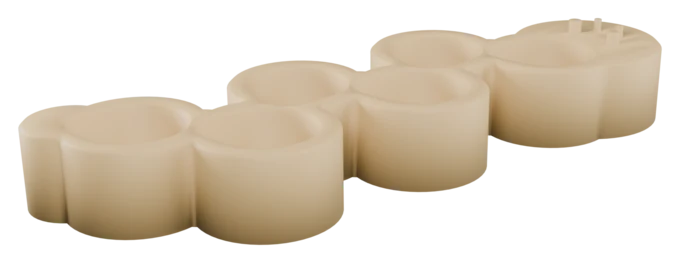
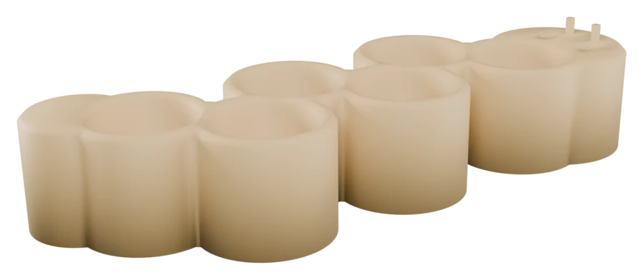
Spinning here in 3D: the caterpillar 18650 holder — a battery caddy shaped like a caterpillar, one of the small functional prints off the plate.

Latest off the plate

A mailbox spacer bigger than the build plate.

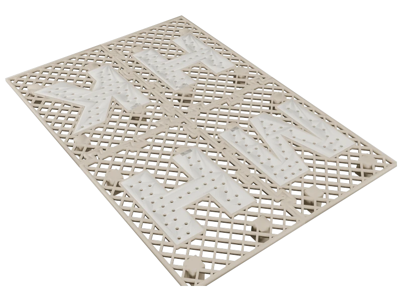
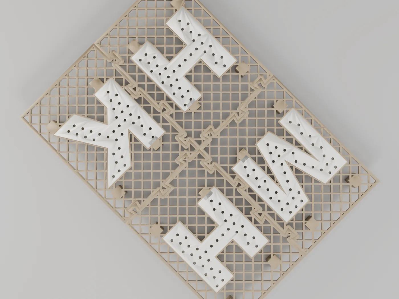
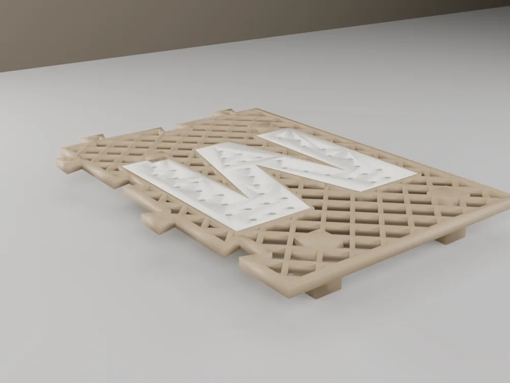
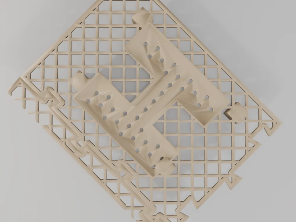
The newest print: a raised stand-off grate for a leaky mailbox that floats the mail about 15 mm above the water pooling on the floor. At 238 × 339 mm it outgrows both the 256 mm bed and the mailbox door, so it prints as four interlocking dovetail-jigsaw quadrants that slot together by hand inside the box — each carrying one two-color letter: M / H / H / K.

Top-down render of the assembled four-piece mailbox stand-off grate — a warm-beige 45-degree cross-hatch drainage mesh with four two-color cream letters (M, H, H, K) peppered with drain holes, arranged around the diagonal dovetail seams
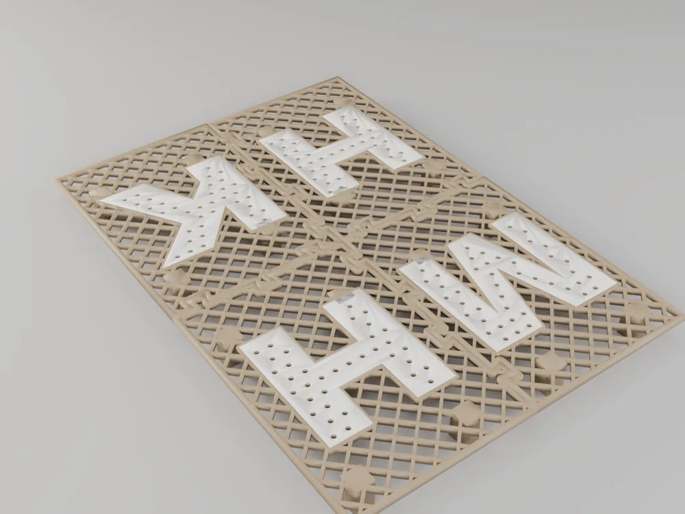
Isometric render of the fully assembled grate, showing its low profile and the four quadrants meeting at the center
assembled — four quadrants
A single quadrant at an angle, showing the stand-off legs beneath the mesh that raise it off the mailbox floor
the stand-off legs
Close-up render of the dovetail-jigsaw joint where two quadrants interlock by hand
dovetail joinery

Two tracks, in parallel

A workflow that earns its keep as it grows.

Most tooling projects build the tool first and find a use for it later. This one does both at once — every real part I need is also a test case that pushes the pipeline somewhere it hasn't been.

The toolkit

An AI-native CAD pipeline, hardening over time

It started as a single agent writing OpenSCAD against a validator. Since then it's grown a second modeling backend (Autodesk Fusion 360 over MCP for organic shapes), an industrial-design critique loop, closed-form strain analysis, slicer-level printability gates, and an automated test-print planner.

The human owns the intent — dimensions, constraints, how parts mate. The pipeline does the CAD and refuses to ship until the geometry passes quantitative review.
The prints

Actual day-to-day stuff I wanted around the house

A fan mount for my mushroom-growing tent. A dock for my label printer. A holder that clips a dumbbell to the treadmill rail. Battery caddies for the drawer, shaped like caterpillars.

None of it is precious. It's the kind of small, functional printing you'd do on any weekend — which is exactly what makes it an honest stress test for the workflow.

From crude bolt-on to organic precision

The build log

Read top to bottom and you can watch the pipeline learn. Each part is dated by when it landed, and tagged with the capability it forced into existence.

Fan-tub adapter v1 — the first real part

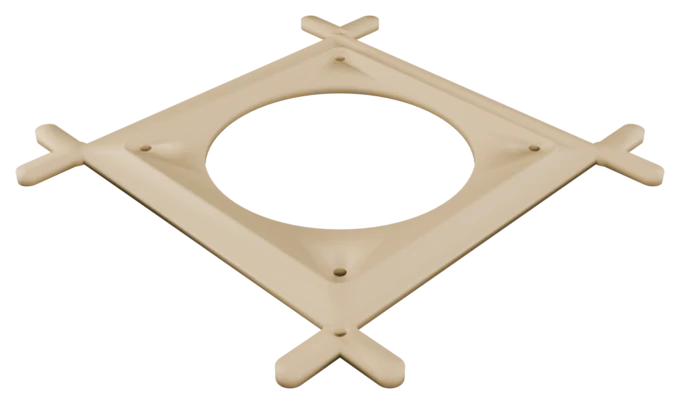
A 119 mm fan mount for the lid of my Martha grow tent. Bolt-on, with a Y-branch waffle engagement, hex-nut counterbores, and a thumbscrew. Crude and over-built — but it fit, and it proved the loop worked end to end.

pushed: first functional print
Render of the v1 bolt-on fan-tub adapter

Snap-fit redesign v2 — zero fasteners

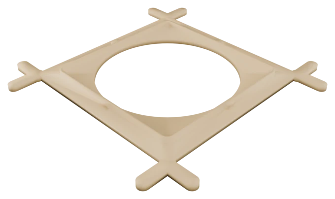
Same fan, reimagined as two parts: a base plate caulked to the lid and a retention clip with cantilever arms that snaps in. No bolts, no thumbscrew. The first time the pipeline had to reason about a multi-part assembly and how the pieces engage.

pushed: designing for assembly
Render of the v2 two-part snap-fit fan-tub adapter base

Humidity duct mount, v1 → v2

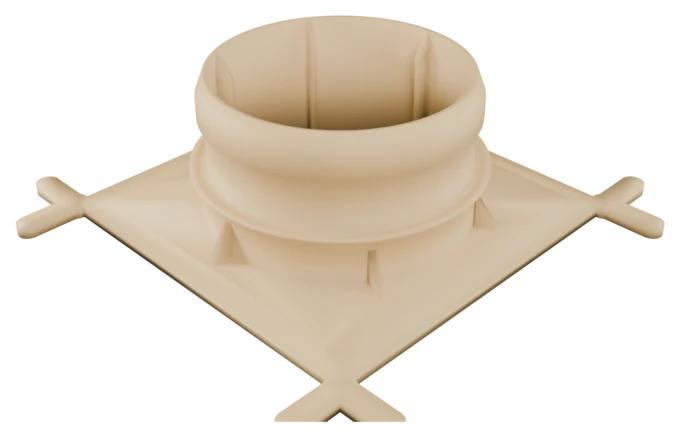
A 4-inch flex-duct mount for HDPE tub lids. V1's spigot came out oversized with no lead-in taper. After test prints, V2 added an EPDM foam seal zone, zip-tie clamping, and a proper lead-in. The first part to go through a real revision — the moment versioning and test prints became part of the routine.

pushed: iterate from test prints
Render of the humidity-output V2 duct mount with lead-in taper and foam seal zone
v2 — supersedes v1

Waffle caulk spudger — a tool for the tools

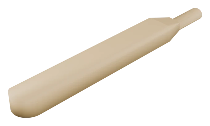
A little handheld spreader whose convex tip lays a smooth caulk bead into the 9.4 mm waffle channels the adapters bond into. Nothing fancy — but it's the workflow building its own jigs to make the other prints come out cleaner.

pushed: bespoke shop tools
Render of the waffle caulk spudger spreading tool

P-touch cradle — quiet industrial design

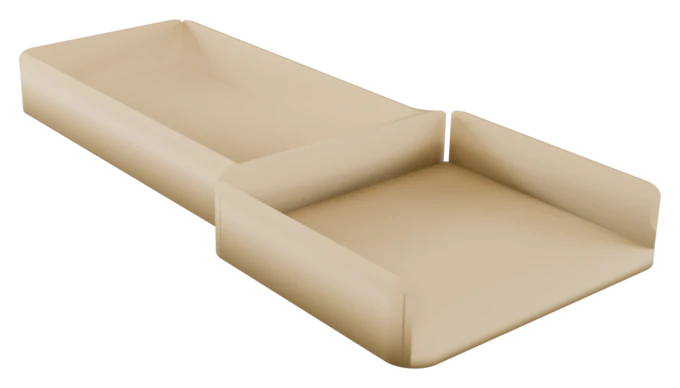
A two-part desk dock for my Brother label printer (the same one behind text-to-tape): a bathtub cradle that holds the printer and a removable tray that catches auto-cut labels. S-curve corner sweeps, a top-edge fillet aligned across both parts. No decoration — just considered.

pushed: aesthetic critique loop
Render of the two-part P-touch cradle and label-catch tray

Dumbbell holder — the second backend goes live

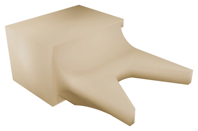
A clip-on for a vertical treadmill rail: a plug inside the extrusion, a sleeve around the outside, and a horizontal slot the dumbbell shaft hangs through. Buttresses, reinforcing ribs, a wall cut away for control-panel clearance. The first part routed to the Fusion 360 MCP backend — freeform geometry the OpenSCAD path didn't want to do.

pushed: Fusion 360 backend
Render of the workout dumbbell holder that clips to a treadmill rail

Battery caddy — modeled twice, on purpose

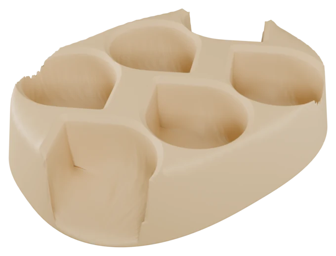
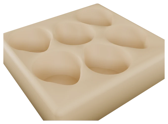
The same 6-capsule drawer rack, built independently by two agents walled off from each other — one in OpenSCAD, one in Fusion. The Fusion agent never saw the .scad, the spec, or the other build's renders, only the problem brief. They produced visibly different bodies (an organic dune-hull vs a soft-filleted slab) yet converged on the same fit-critical numbers: 0.35 mm socket clearance, 2.0 mm minimum wall. Proof the review gates — not the modeling tool — decide what's correct.

pushed: backend-agnostic proof
OpenSCAD battery caddy — organic dune-hull rack with six nested teardrop sockets
OpenSCAD
Fusion battery caddy — soft-filleted rounded slab with six staggered sockets
Fusion

Caterpillar holders — peak, so far

The battery rack reimagined as a zig-zag caterpillar: a segmented body, a rounded head with eye dimples and antenna nubs, a tapered tail. Two variants — one for capsules, one for bare 18650 cells with nipple-indent floors so button-tops seat positive-side-down. Watertight, prints flat, support-free. Playful form sitting on top of functional precision.

pushed: organic + functional
Render of the caterpillar capsule holder, a segmented zig-zag body with six teardrop sockets

Mailbox stand-off grate — bigger than the build plate

A raised drainage grate for a leaky mailbox — it floats the mail about 15 mm above the water that pools on the floor. At 238 × 339 mm it outgrows both the 256 mm bed and the mailbox door, so it prints as four interlocking dovetail-jigsaw quadrants that slot together by hand inside the box. A continuous 45° cross-hatch mesh (~46% open) drains freely; each quadrant carries one mostly-solid two-color letter — M / H / H / K. The first part the pipeline had to fracture to fit its own constraints.

pushed: splitting a part past the build volume
Render of the assembled four-piece mailbox stand-off grate — warm-beige cross-hatch drainage mesh with two-color cream M/H/H/K letters peppered with drain holes

For the engineers

It doesn't ship until the geometry passes review.

Specialized agents split the work — each owns one stage, talks through structured files, and never sees the full conversation. Two stages are opt-in per part: an industrial-design loop for visible parts, and strain analysis for load-bearing ones.

Pipeline diagram: spec-writer creates requirements; modeler or modeler-fusion generate geometry with an optional id-designer aesthetic pass; geometry-analyzer slices the mesh; fit-reviewer checks assemblies; strain-analyzer runs beam theory on load-bearing parts; print-reviewer gates on FDM limits — pass continues to test-print-planner, fail loops back to the modeler; shipper publishes with Blender hero renders
The pipeline, kept in sync with the repo's AGENT-WORKFLOW.md

Ground-truth printability

trimesh slices the rendered mesh at every layer height; PrusaSlicer confirms support and bridge behavior from the actual G-code. Bridges get classified as functional or avoidable — the reviewer isn't guessing from the model, it's reading the slice.

slice

Automated print review against FDM limits

Every feature transition, overhang, bridge, wall thickness, and mating clearance is checked against FDM/PLA limits before a part ships. A fail loops back to the modeler with specifics; a pass continues to test-print planning.

review

Closed-form strain analysis

Load-bearing parts declare a load case. The analyzer runs beam theory — σ = Mc/I — against the declared critical sections, applies an FDM interlayer derate, and reports safety factors and tip deflection. When the closed-form margin is tight, it flags for FEA rather than waving it through.

strain

Test prints before the full commit

Critical fitment interfaces — tight tolerances, near-limit overhangs, novel features — get broken out into minimal-material, hollow test pieces. You verify the fit in your hand before committing filament and hours to the full part.

verify

Still cooking

It's not finished — that's the point

An evolving experiment has loose ends on purpose. Here's what's mid-flight.